• Thank you for visiting HeavyEquipmentForums.com! Our objective is to provide industry professionals a place to gather to exchange questions, answers and ideas. We welcome you to register using the "Register" icon at the top of the page. We'd appreciate any help you can offer in spreading the word of our new site. The more members that join, the bigger resource for all to enjoy. Thank you!

CAT 938f quad gauge issues

Nige

Senior Member
Joined
Jun 22, 2011
Messages
38,690
Location
G..G..G..Granville.........!! Fetch your cloth.
See if you can find twisted pair of wires going to that module, check the connection, put the ohmmeter across them and measure resistance should be 60 ohm. If it is 120 ohm - you have problems with terminating resistor.
No terminating resistors on this machine. It's far too old. It uses Cat's proprietary Datalink not the latest generation of CAN Datalink.
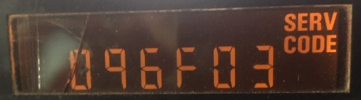
So Serv icon stays illuminated and lists the following codes
I see a lot of photos but not one of them with the SERV CODE icon lit indicating that the Code on the screen is Active. Can you possibly try again please, starting with a photo of the Monitor Panel taken with the engine idling showing the SERV CODE icon lit up. Having the engine running will remove the likelihood of any spurious low voltage Codes that may be present when the engine is stopped.

The image below shows an Active Code.

1738279819745.png

Each Code will appear in two consecutive screens as follows MID (030, 081), CID (110, 248, 621) and FMI (02, 08).
 

TVA

Senior Member
Joined
May 14, 2018
Messages
2,862
Location
USA
Dang Nige! Im feeling young all of the sudden! :)
Talking 1939 here!
 

Caincon

Member
Joined
Jan 25, 2025
Messages
14
Location
MA
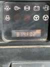
Nige Apologize for delay… I show one active code with service icon illuminated . Let machine run for approx 5 min to eliminate any possible low voltage codes .IMG_2463.jpegIMG_2462.jpeg
 

TVA

Senior Member
Joined
May 14, 2018
Messages
2,862
Location
USA
Look up thread here called “cat monitoring system”
 

Nige

Senior Member
Joined
Jun 22, 2011
Messages
38,690
Location
G..G..G..Granville.........!! Fetch your cloth.
OK, so now we are getting somewhere. You have 819 F02 which relates to the transfer of information to/from the principal Monitor Module and the Quad Gauge Module and the Speedo/tacho (if equipped) module.

See the attached troubleshooting procedure. Also check your message inbox for an electrical schematic.
You're going to be digging into the dash panel........
 

Attachments

  • MID030 CID0819 FMI02 (2).pdf
    161.6 KB · Views: 6

TVA

Senior Member
Joined
May 14, 2018
Messages
2,862
Location
USA
Or contamination in the (unused) connector on the branch of the harness to the speedo/tacho module.
Or maybe even crusties in the Main Monitor module harness connector.
You are correct.Everything needs to be checked out, diligently.
 

Caincon

Member
Joined
Jan 25, 2025
Messages
14
Location
MA
Nige, we have gone through testing procedure. I’m going to have a friend who’s a mechanic go over test with us Again and see if we have any different results , as of now we did entire procedure , have found no broken wires , no corrosion. No chafes , nothing indicating that we have a wiring issue. I’m not brain dead , but I also wouldn’t consider myself a master mechanic and would like a second set of eyes to
Go through procedure . Have you ever seen the message center module fail? We made
It to step 5 and have 9 volts to message center module.
 

TVA

Senior Member
Joined
May 14, 2018
Messages
2,862
Location
USA
Is anything “aftermarket” installed close to the cluster. Some kind of high power or high frequency device? That can produce EMI, or any kind of wires goes through it?
 

Caincon

Member
Joined
Jan 25, 2025
Messages
14
Location
MA
Nothing aftermarket , no speedometer or tac in this machine, nothing inside this machine has been messed with. We are third owner bought from a friend. We did add a radio with factory harness. No difference with radio
Installed or prior to .
 

TVA

Senior Member
Joined
May 14, 2018
Messages
2,862
Location
USA
Radio is just a receiver - it wouldn’t emit EMI

Maybe I’m fantasizing here, it’s my Industrial Control and Communications experience kicked in.
 

Nige

Senior Member
Joined
Jun 22, 2011
Messages
38,690
Location
G..G..G..Granville.........!! Fetch your cloth.
Did the procedure direct you to the conclusion that the Message Centre module is bad.?
Step 5 is a bit confusing, even to me and I know my way around it well. Note the title of the Step - "CHECK FOR + 12 DCV."
You are looking for the presence of +12v DC, or battery voltage if you prefer.. That is what the module is supposed to be outputting if everything works as it should.

If you see 9.0 ± 0.5 DCV then the Monitor Module has failed.
Back to my question of what Part Number is marked on the module in your particular loader.
 

Nige

Senior Member
Joined
Jun 22, 2011
Messages
38,690
Location
G..G..G..Granville.........!! Fetch your cloth.
Try a couple of simple tests.

1. Unplug the Quad Gauge module from the machine harness. Turn the key ON and measure the voltage again by pack-probing between Pins 1 & 2 of the Main Monitor Module connector.

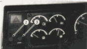
2. Quad Gauge remains unplugged. In the dash panel remove the lamps #2 & #3 from the Ride Control Indication and the Auto Ride Control. Key ON and again measure voltage between Pins 1 & 2.

1738441263958.png

For both of the above tests are you still measuring 9.0v.?
 
Top