• Thank you for visiting HeavyEquipmentForums.com! Our objective is to provide industry professionals a place to gather to exchange questions, answers and ideas. We welcome you to register using the "Register" icon at the top of the page. We'd appreciate any help you can offer in spreading the word of our new site. The more members that join, the bigger resource for all to enjoy. Thank you!

Toyota 7FGU30 No crank/No start please help

WaelB

Active Member
Joined
Feb 19, 2026
Messages
35
Location
Bakersfield, CA
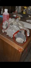
I am assuming that you are referring to the solenoid on the LPG regulator. Attached is a photo of the regulator. The solenoid marked #1, I can hear that click when cranking. The one marked #2, I cannot. Not sure what this one is.

Also I should mention that the LPG regulator is new. It was recently replaced. The photo is of the old one but they are the same.
 

Attachments

  • IMG_0304.jpeg
    IMG_0304.jpeg
    404.6 KB · Views: 4
Last edited:

Simon C

Senior Member
Joined
Jul 1, 2015
Messages
2,990
Location
Rocky Mountain House , AB., Canada
Occupation
Heavy Equipment Mechanic
Okay so on schematic 16-27 you will find the LPG Relay and the LPG solenoid. It is the solenoid that will release propane into the engine. There is a 7.5 amp fuse that feeds it after the Ignition switch on the schematic. Have a look at that part and I cannot say where the relay is but the solenoid for the propane should be under the hood somewhee with a pipe that goes to mixing chamber then carburetor.
Simon C
 

Simon C

Senior Member
Joined
Jul 1, 2015
Messages
2,990
Location
Rocky Mountain House , AB., Canada
Occupation
Heavy Equipment Mechanic
Sorry about that, and yes one of those will let the propane through. I am not no propane expert but I would think that one of them will get it going if the coil actually works internally.
Did you by any chance change a propane bottle lately that had an extra sealing rubber in the hose connection stopping the gas from exiting the tank. With no flamables around you could crack the propane line coming towards the solenoid with good welders mitts on so as not to get burn't from the cold to ensure you have gas to the valve. I will check schematic for the other valve which may be some kind of shut -off, not sure.
Need to start somewhere.
Simon C
 

Simon C

Senior Member
Joined
Jul 1, 2015
Messages
2,990
Location
Rocky Mountain House , AB., Canada
Occupation
Heavy Equipment Mechanic
The LPG solenoid is fed by wire ( BY - should be black and yellow ), the ground goes to earth by wire ( W/B which should be White/black ). Your plug will show which is which and mark with black marker pen on the Solenoid to remember. The solenoid could click and not open the valve is a possiblity.
Check if there is power to the B/Y wire while cranking.
Hope we get it figured out.
Simon C
 

WaelB

Active Member
Joined
Feb 19, 2026
Messages
35
Location
Bakersfield, CA
Sorry about that, and yes one of those will let the propane through. I am not no propane expert but I would think that one of them will get it going if the coil actually works internally.
Did you by any chance change a propane bottle lately that had an extra sealing rubber in the hose connection stopping the gas from exiting the tank. With no flamables around you could crack the propane line coming towards the solenoid with good welders mitts on so as not to get burn't from the cold to ensure you have gas to the valve. I will check schematic for the other valve which may be some kind of shut -off, not sure.
Need to start somewhere.
Simon C
Yes we did crack one of the propane lines at the regulator and it did shoot out propane.
 
Last edited:

WaelB

Active Member
Joined
Feb 19, 2026
Messages
35
Location
Bakersfield, CA
Okay so on schematic 16-27 you will find the LPG Relay and the LPG solenoid. It is the solenoid that will release propane into the engine. There is a 7.5 amp fuse that feeds it after the Ignition switch on the schematic. Have a look at that part and I cannot say where the relay is but the solenoid for the propane should be under the hood somewhee with a pipe that goes to mixing chamber then carburetor.
Simon C
Gotcha, I will check again later this week on that. I’ll try to drag the lift outdoors. Currently it’s in a very dark warehouse and my eyes are not what they used to be even with a work light
 

WaelB

Active Member
Joined
Feb 19, 2026
Messages
35
Location
Bakersfield, CA
The LPG solenoid is fed by wire ( BY - should be black and yellow ), the ground goes to earth by wire ( W/B which should be White/black ). Your plug will show which is which and mark with black marker pen on the Solenoid to remember. The solenoid could click and not open the valve is a possiblity.
Check if there is power to the B/Y wire while cranking.
Hope we get it figured out.
Simon C
Thank you Simon, I will check everything you suggested thoroughly. Unfortunately I won’t be able to do it till maybe Friday as I have other commitments. But if you would please keep an eye on this thread and I will reply back just as soon as I have the info.
 

Simon C

Senior Member
Joined
Jul 1, 2015
Messages
2,990
Location
Rocky Mountain House , AB., Canada
Occupation
Heavy Equipment Mechanic
Thank you Simon, I will check everything you suggested thoroughly. Unfortunately I won’t be able to do it till maybe Friday as I have other commitments. But if you would please keep an eye on this thread and I will reply back just as soon as I have the info.
At your pace. Better to do some diagnostics and small wiring repairs before firing the parts cannon.
Simon C
 

WaelB

Active Member
Joined
Feb 19, 2026
Messages
35
Location
Bakersfield, CA
Simon, I got a thought. That second solenoid in the regulator that I asked you about, can it be a low fuel cutoff? I did some googling for a fuel cutoff solenoid for this lift and I came across part number 23620-23340-71 and it looks like the correct solenoid. I think I need to check power to this (along with all your other suggestions). If it is a fuel cutoff, supposedly there should be a relay that controls it so I’ll have to trace the wires back and see what relay it goes to and test there again. I’m thinking I might be able to just apply power to that solenoid and see what happens. But I do know that at no time do I ever hear this solenoid click. I’m referring to the one marked #2 in the photo
 

Attachments

  • IMG_0304.jpeg
    IMG_0304.jpeg
    404.6 KB · Views: 2

Simon C

Senior Member
Joined
Jul 1, 2015
Messages
2,990
Location
Rocky Mountain House , AB., Canada
Occupation
Heavy Equipment Mechanic
Found it on PG.16-40. There is a low pressure propane switch, relay, warning lamp.
Maybe one of them is defective and no flash of engine. Have a look and you will need to do some checking.
In my previous explanation about ground cables an easier way to remember is, if the ground cable is disconnected from Battery Negative Post then the cable is still positive, if the cable or wire is connected to Battery Negtative post it will be Negative when checking, because the energy used to turn fan or light bulb has been spent and only amps are going back to battery.
Simon C
 

WaelB

Active Member
Joined
Feb 19, 2026
Messages
35
Location
Bakersfield, CA
The LPG solenoid is fed by wire ( BY - should be black and yellow ), the ground goes to earth by wire ( W/B which should be White/black ). Your plug will show which is which and mark with black marker pen on the Solenoid to remember. The solenoid could click and not open the valve is a possiblity.
Check if there is power to the B/Y wire while cranking.
Hope we get it figured out.
Simon C
Yes power to the black/yellow wire while cranking. I tested the black/yellow coming out of the back of the ign switch. Probably not where you wanted me to test. Still trying to locate the black and yellow going to the relay.
 
Last edited:

WaelB

Active Member
Joined
Feb 19, 2026
Messages
35
Location
Bakersfield, CA
Hi Simon, I have some good info. There were two relays mounted on a bracket adjacent to the main fuse box. I unplugged both these relays from their connectors and jumpered a paper clip across the contact terminals of the connector. The forklift cranked and started. I’m not sure what these two relays are for or why they are not getting energized. I’ve taken photos of the relay connectors hoping to show the colors of the wires going to them. I will look at the schematic and try to find them but I think this is good progress. Attached are the photos. I took two photos of each (bottom side and top side) to better show the wires
 

Attachments

  • IMG_0337.jpeg
    IMG_0337.jpeg
    786.5 KB · Views: 3
  • IMG_0336.jpeg
    IMG_0336.jpeg
    869.1 KB · Views: 3
  • IMG_0335.jpeg
    IMG_0335.jpeg
    1.1 MB · Views: 3
  • IMG_0334.jpeg
    IMG_0334.jpeg
    1.1 MB · Views: 3

Simon C

Senior Member
Joined
Jul 1, 2015
Messages
2,990
Location
Rocky Mountain House , AB., Canada
Occupation
Heavy Equipment Mechanic
Hi Simon, I have some good info. There were two relays mounted on a bracket adjacent to the main fuse box. I unplugged both these relays from their connectors and jumpered a paper clip across the contact terminals of the connector. The forklift cranked and started. I’m not sure what these two relays are for or why they are not getting energized. I’ve taken photos of the relay connectors hoping to show the colors of the wires going to them. I will look at the schematic and try to find them but I think this is good progress. Attached are the photos. I took two photos of each (bottom side and top side) to better show the wires
So just from experience you could simply have some dirty plug ins. They do look fairly dirty to me, and could use some high pressure air to clean out. Also good to check all female pin receivers to see if one pin is a little loose. Have seen too many times to remember especially if lots of hours.
Page (16-40) had the propane solenoids and valves.
Might be an idea to clean as many connectors as possible to rule out loose pins or corroded contacts in a plug.
Simon C
 

WaelB

Active Member
Joined
Feb 19, 2026
Messages
35
Location
Bakersfield, CA
Yes just about every connector I disconnected was really dirty. I did take some starter spray and cleaned out all the ones I disconnected before plugging back in but I will go through them all and check for loose pins as well. At this point I’m trying to identify those relays in the schematic based on the wire colors going to them. But unfortunately I haven’t been able to identify them yet.
 

Simon C

Senior Member
Joined
Jul 1, 2015
Messages
2,990
Location
Rocky Mountain House , AB., Canada
Occupation
Heavy Equipment Mechanic
Be mindful of relays with 4 or 5 pins. There needs to be only 1 loose pin receiver for a relay to not work.
I have some different pins for testing all female receivers to make sure they are all tight.
Simon C
 

WaelB

Active Member
Joined
Feb 19, 2026
Messages
35
Location
Bakersfield, CA
These relays all have 4 pins (2x coil & 2x contacts). These are both Normally open relays. The relays themselves are good. Tested with multimeter.
 

Simon C

Senior Member
Joined
Jul 1, 2015
Messages
2,990
Location
Rocky Mountain House , AB., Canada
Occupation
Heavy Equipment Mechanic
Just to tell you how prevalent it is , loose pins. I have a customer with Case TV380 Track machine that would start and die from blown fuse within 2 minutes of running.
I changed the relay that was associated with the blown fuse and still blew the fuse.
So I proceeded to slowly tighten all the female receivers of the relay and all the relays around.
That was 2.5 years ago and the machine has never died since.

Another thing to watch out for is Relays with Normally closed contacts that look exactly the same as those with normally open contacts. Ran into this about 3 weeks ago, and it was not the problem. A diode installed backwards was the problem.
Need to dot every I and cross every TEE.
Simon C
 

WaelB

Active Member
Joined
Feb 19, 2026
Messages
35
Location
Bakersfield, CA
The relays are the same ones that have always been in it when it was running previously. I removed them and used a 9v battery to test them as to not blow the internal snubber diode. Using my fluke, I put the meter in continuity mode and clipped alligator clips to the contact terminals of the relay itself. When energized with the 9v battery with polarity correct, the relay clicks and I have continuity through my meter. So both these relays are functioning. They are normally open relays. But as you mentioned, I need to more carefully check for loose pins. I didn’t see or feel any but it’s possible I could have overlooked something either on those relays or somewhere else. By the way, I did previously unplug every relay in the machine and test the relays in the same manner mentioned above. It was time consuming but they all tested good. We’re getting closer for sure. I just wish I knew what exactly I jumpered when I jumpered the contact terminals on those relays and the machine started and ran. I’m beginning to think that maybe these schematics I have are not the right ones for some reason. I can’t seem to find the corresponding colors. I have to any of the relays in the schematic.
 
Top