Chris5500
Well-Known Member
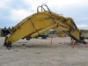
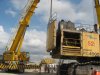
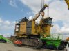
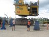
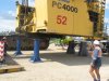
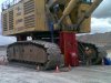
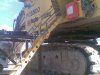
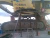
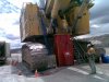
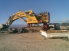
I was going to post photos of the KMG (Komatsu Mining Germany) factory where the PC3000, 4000, 5500 and 8000's are made. Apart from Komatsu and Demag machines, the factory started its life as a Nazi war factory during WW2. Anyway, I've lost the photo's and while searching I came across these which I'd like to share with you because not many (if any at all) have been exposed to such maintenance activities and for some people these will be quite interesting.
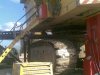
Title says it all really...
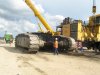
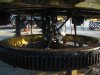
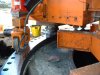
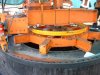
For those of you who saw the ones that Gav posted on DHS a while back of the 5500 slew ring change (will post photos if requested) you will notice that it’s a completely different procedure. Reason being is that this machine is part of a marked contract and as per the Komatsu slew ring procedure the bearing mounting surface must be measured (and machined if required) and has to be within 0.4mm (0.015inch) in order for KMG to warrant the new slew ring, as it happens this particular one was out by +0.12-0.18mm and had to be remachined. As the 5500 was not part of a marked contract it was the owner’s decision to take a chance and fit it without measuring or machining (correct me if I’m wrong Gav!)
Feel free to ask any questions you may have... hopefully some technical ones")
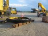
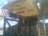
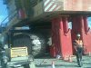
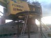
Title says it all really...
For those of you who saw the ones that Gav posted on DHS a while back of the 5500 slew ring change (will post photos if requested) you will notice that it’s a completely different procedure. Reason being is that this machine is part of a marked contract and as per the Komatsu slew ring procedure the bearing mounting surface must be measured (and machined if required) and has to be within 0.4mm (0.015inch) in order for KMG to warrant the new slew ring, as it happens this particular one was out by +0.12-0.18mm and had to be remachined. As the 5500 was not part of a marked contract it was the owner’s decision to take a chance and fit it without measuring or machining (correct me if I’m wrong Gav!)
Feel free to ask any questions you may have... hopefully some technical ones