• Thank you for visiting HeavyEquipmentForums.com! Our objective is to provide industry professionals a place to gather to exchange questions, answers and ideas. We welcome you to register using the "Register" icon at the top of the page. We'd appreciate any help you can offer in spreading the word of our new site. The more members that join, the bigger resource for all to enjoy. Thank you!

955L Alternator Wiring

hot_rod_eddie

Well-Known Member
Joined
Dec 15, 2020
Messages
52
Location
North Carolina
Good evening guys,
So I have had my 1976 955L for a few years. When I first got it, none of the electrical system would work except start. No glow plugs, no lights, no alternator. Everything was crusty or burnt, etc. Using the previous wiring harness, and the wiring schematic from Cat (see attachment) I made a new harness. Installed new gauges, etc. Everything seemed to work fine as I hooked the wires up in stages. However, when I wired up the alternator the circuit breaker popped. I took the alternator apart and it looked burnt inside. So for the past couple of years I have been running without an alternator. I finally got tired of carrying a battery charger and generator every time I want to use my machine, so I bought myself a new alternator this Christmas.
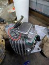
So here is my issue. According to the way the "as-found" alternator was wired, two wires come from the ammeter to the charge post on the alternator. This is the same as is shows on the drawing from Cat. No other wires. The new alternator I bought has what appears to be different posts, so I called the manufacture to inquire. They verified that the alternator I bought is for my machine. However, they said that the alternator isn't self excited unit so it would have to have key switch power to one of the posts. I tried to explain that this machine doesn't have key switch power, just a momentary switch to start. They guy was very nice and helpful as he could be, but we didn't come up with a solution.

I have been sitting here wondering a couple things.
1. Why would there be two 8 gauge wires running from the ammeter to the alternator. Is it just to reduce the size of wire? Was one wire supposed to go to the charge post and one to the excitation post?

or

2. Are both wires supposed to go the charge post, and I make a jumper from the charge post to the excitation post.

If it is #2, would you recommend putting a diode in the jumper wire?

What does the brain trust think?
Thank you


1737766353313.png
 

hot_rod_eddie

Well-Known Member
Joined
Dec 15, 2020
Messages
52
Location
North Carolina
Quick update. The post the manufacture said was the excitation post can't be right. That post has continuity with the alternator case.
 

TVA

Senior Member
Joined
May 14, 2018
Messages
2,862
Location
USA
Send a picture of alternator itself.
Old machine was converted to Delco SI alternators from original left and right. We need to see what you have.
You can jump exciter to B+ post, but make sure that you will shut down main switch, because it’ll be discharging your batteries.

If it’s SI type of alternator - you can buy self exciting regulator for it.

if you have ammeter - everything goes trough there, or trough shunt resistor, if your current exceeds ammeter rating.

Exciting winding does have continuity to ground, because everything need to have positive and negative, unless your running over voltage, and regulator disconnect grind to stop exciting and consequently charging.
 
Last edited:

TVA

Senior Member
Joined
May 14, 2018
Messages
2,862
Location
USA
One of the wires from ammeter should go back to battery positive post, or to starter where cable from the battery positiive post comes from.
And according to the diagram - it does that through circuit breaker.
 
Last edited:

hot_rod_eddie

Well-Known Member
Joined
Dec 15, 2020
Messages
52
Location
North Carolina
Send a picture of alternator itself.
Old machine was converted to Delco SI alternators from original left and right. We need to see what you have.
You can jump exciter to B+ post, but make sure that you will shut down main switch, because it’ll be discharging your batteries.

If it’s SI type of alternator - you can buy self exciting regulator for it.

if you have ammeter - everything goes trough there, or trough shunt resistor, if your current exceeds ammeter rating.

Exciting winding does have continuity to ground, because everything need to have positive and negative, unless your running over voltage, and regulator disconnect grind to stop exciting and consequently charging.
Here you go. They said the big terminal on the left beside the orange wire is the charge post (battery/ammeter). The small post beside the green wire is supposed to be excitation. If I jump a wire from the charge post to the exciter post, do you recommend installing a diode? One thing I can't get my head around about your statement on the exciter post. It is a dead short (I used the term continuity above) to the case 0.0 ohm. Seems that if I put a 12v there, it will be a dead short.
The alternator is a 20amp and the circuit breaker is 60 amp. Do you recommend putting a shunt resister in the circuit? The wiring diagram above doesn't show any resister.
Thank you.
 

Attachments

  • Alternator.jpg
    Alternator.jpg
    329.7 KB · Views: 24
Last edited:

TVA

Senior Member
Joined
May 14, 2018
Messages
2,862
Location
USA
Dead short is not good. Maybe failed regulator.
I’m not familiar with those. Do you have brand and model?

No, I’m pretty sure your ammeter should go at least to 30 amp.
 

TVA

Senior Member
Joined
May 14, 2018
Messages
2,862
Location
USA
I’m not sure, but i think you should connect your exciter feed to the small post next to the top of the alternator, next to green wire.

Seems like regulator is making and breaking connection to the ground.

Basically you want to put your excitement feed to one of the brushes to the rotor, the other side should be connected to the ground. And somewhere circuit should get interrupted when regulator senses over voltage on stator output.
 

TVA

Senior Member
Joined
May 14, 2018
Messages
2,862
Location
USA
I just found the picture and looks like there’s a copper strap connected to the small post next to the one with green wire. So that one is the rotor ground.
Green wire is regulating feed to the rotor from the regulator.

Does the post with orange wire have isolating plastic bushing, like the B+ does?

If you remove the orange wire from the post, and go straight to it - does it have dead short to the ground? Or will it show some resistance?
 

tctractors

Senior Member
Joined
Oct 9, 2007
Messages
2,564
Location
Worc U.K.
The Alternator looks nothing like I have seen before but as a way of exciting it just below the bottom of the injector pump towards the gear chest is a plug you can remove from the oil gallery and fit in a 2 wire oil pressure switch with a live feed to it so with engine stopped the feed off it can be used to excite the Alternator, when the engine starts the oil switch goes open job sorted, this method was used for years on D8H 951C etc so its well proven, also a live feed can be taken from the starter motor crank side so it's only fed power under cranking conditions with a little inline fuse.
 

hot_rod_eddie

Well-Known Member
Joined
Dec 15, 2020
Messages
52
Location
North Carolina
The Alternator looks nothing like I have seen before but as a way of exciting it just below the bottom of the injector pump towards the gear chest is a plug you can remove from the oil gallery and fit in a 2 wire oil pressure switch with a live feed to it so with engine stopped the feed off it can be used to excite the Alternator, when the engine starts the oil switch goes open job sorted, this method was used for years on D8H 951C etc so its well proven, also a live feed can be taken from the starter motor crank side so it's only fed power under cranking conditions with a little inline fuse.
That is a pretty cool idea. I was thinking worst case scenario I put on a crank trigger. :)
 

hot_rod_eddie

Well-Known Member
Joined
Dec 15, 2020
Messages
52
Location
North Carolina
I just found the picture and looks like there’s a copper strap connected to the small post next to the one with green wire. So that one is the rotor ground.
Green wire is regulating feed to the rotor from the regulator.

Does the post with orange wire have isolating plastic bushing, like the B+ does?

If you remove the orange wire from the post, and go straight to it - does it have dead short to the ground? Or will it show some resistance?
You are correct there is a strap on that post near the green wire. There is no letter on it or near that post.
I will check the orange post for an isolator in .the morning. I will also check post to chassis, wire to chassis.
Thank for the help.
 

TVA

Senior Member
Joined
May 14, 2018
Messages
2,862
Location
USA
If the orange wire doesn’t have dead short to ground - you can try and use it off of that post, just connect to the feeding wire directly, without mounting it to the post.
 

hot_rod_eddie

Well-Known Member
Joined
Dec 15, 2020
Messages
52
Location
North Carolina
Update - about 20ohms between green wire post and bare post beside it. No continuity between the green post and anything else. Orange post has an isolator, and no continuity between the orange post and anything else.

I am going to hook up only to the charge post. If that doesn't work I will run a jumper from charge post to orange post.

Side note: I bought the alternator from Romaine Electric. I googled their part number 7331 and found one for a Prestolite alternator. I have heard of Prestolite so I called them. They guy told me they haven't made that style alternator in many years, and even then it didn't look like the one online. Interesting...
 

TVA

Senior Member
Joined
May 14, 2018
Messages
2,862
Location
USA
Update - about 20ohms between green wire post and bare post beside it. No continuity between the green post and anything else. Orange post has an isolator, and no continuity between the orange post and anything else.

I am going to hook up only to the charge post. If that doesn't work I will run a jumper from charge post to orange post.

Side note: I bought the alternator from Romaine Electric. I googled their part number 7331 and found one for a Prestolite alternator. I have heard of Prestolite so I called them. They guy told me they haven't made that style alternator in many years, and even then it didn't look like the one online. Interesting...
It kinda look like Prestolite - but i guess that thing so old, so I couldn’t find anything on it.
 

hot_rod_eddie

Well-Known Member
Joined
Dec 15, 2020
Messages
52
Location
North Carolina
Sorry I never updated this post. I installed the alternator and connected both wires to the charge post. Alternator works great. Can see negative amps when using glow plugs, the positive amps for a few minutes after start up.
 
Top