• Thank you for visiting HeavyEquipmentForums.com! Our objective is to provide industry professionals a place to gather to exchange questions, answers and ideas. We welcome you to register using the "Register" icon at the top of the page. We'd appreciate any help you can offer in spreading the word of our new site. The more members that join, the bigger resource for all to enjoy. Thank you!

Identifying Parts Case 1845C

kingmt

Member
Joined
Jun 2, 2017
Messages
17
Location
elsewhere
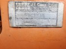
I have two questions about an older 1845 C.

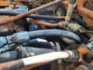
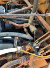
There is what looks like a pressure switch under the seat. It is on the side of a T fitting close to the filter. Mine isn't connected but it seems like it went to an indicator light. Can someone identify this & why it is needed?

I think my overall pressure is set too high. Where is the adjustment for this?
 

kshansen

Senior Member
Joined
Mar 11, 2012
Messages
11,208
Location
Central New York, USA
Occupation
Retired Mechanic in Stone Quarry
Best I can offer right of is this link to an online parts book for the 1845C:


One thing I noticed from the pictures is to me that does not look like what I recall the drive pump set-up on a 1845C actually looks like the drive pumps for a 1845.

What I referring to is the two valves on the pumps that you can turn to allow the machine to be towed. I have put a red arrow in the picture pointing to one of them.

1845.jpg

That could be the reason I'm not seeing that pressure switch( yellow wire) in the parts book for a 1845C .

One more note I have an old 1845 parts book dated Jan. 1980 and it shows that Tee connection that the pressure switch of yours in mounted in but in my parts book it shows an 1/8 inch pipe plug in the hole.
 

kingmt

Member
Joined
Jun 2, 2017
Messages
17
Location
elsewhere
After looking I believe it is an 1845 myself. I guess I have been lucky in the parts that I have bought so far.

That link was useful but I wish they gave a better name for parts than "valve" & so on...

Mine has since I've owned it made a loud noise. It is hard to explain but it sounds like pressure screaming. I did do it all the time but now it does it only when there is pressure driving the wheels. When I try to turn it gets the loudest. If I try to turn sharply it feels like it binds up & stalls. I have to move the levers back & forth to release this pressure before I can get it to turn over.

I have it striped right now redoing the electrical & addressing what I believe was a fuel problem & was hoping I could take care of this noise while I have it apart.
 

kshansen

Senior Member
Joined
Mar 11, 2012
Messages
11,208
Location
Central New York, USA
Occupation
Retired Mechanic in Stone Quarry
Looked a bit more in the old parts book in electrical section and there it shows a "sending unit", pressure, hydraulic oil at that location, see #7 in red box.

There are also shown on that page three indicator lights on what appears to be a panel on the right support for the ROPS. One is Change Filter light, one is Transmission Temperature and the last Charge Pressure, this one is circled in green in image below. On this page you can see the hydraulic filter has a wire connected to the top, this would be for the filter light.

1845 Electrical.jpg

So best I can tell is that sender in your picture has only a function of turning a light on or off, assume it would turn on the warning light if charge pressure for drive pump dropped too low. Guess what I'm trying to say is machine would operate correctly "IF" that sender was not working, but if the charge pressure was not correct you might not know it. Does that make sense?

So far I have not been able to find any spec's for that sending unit other than the part number D69775 and don't have any real idea of what the normal charging pressure would be for those pumps.
 

kingmt

Member
Joined
Jun 2, 2017
Messages
17
Location
elsewhere
The yellow wire is the only thing in that harness that is still connected & only to the switch I showed.

I was wondering earlier what that was in the green circle. The terminal is gone & it leaks. Whatever was in the top has been replaced as well.

There is no wire going to the filter but I will have to take a closer look to see if there is a place for one.

Is this picture for a gas engine? #2 looks like a ballast which I do not have.
 

kshansen

Senior Member
Joined
Mar 11, 2012
Messages
11,208
Location
Central New York, USA
Occupation
Retired Mechanic in Stone Quarry
The yellow wire is the only thing in that harness that is still connected & only to the switch I showed.

I was wondering earlier what that was in the green circle. The terminal is gone & it leaks. Whatever was in the top has been replaced as well.

There is no wire going to the filter but I will have to take a closer look to see if there is a place for one.

Is this picture for a gas engine? #2 looks like a ballast which I do not have.
Parts book is a bit vague in that area, but I believe that is just a junction block where a couple or three hydraulic lines couple together. The top port(as it is in the drawing) would be the point the hydraulic temp gauge is installed and the bottom is where the sender that works the turns on the warning light if oil gets too hot.

The parts book is for both the gas and diesel engine models so you have to be careful and read the disruptions as they use one picture for both!

Is there still the serial number tag on your machine? According to my book it should be left hand side of the heel plate, I think what the call the "heel plate" is if you were sitting in the machine and pulled you left foot back it's the wall your heel would hit.
 
Top